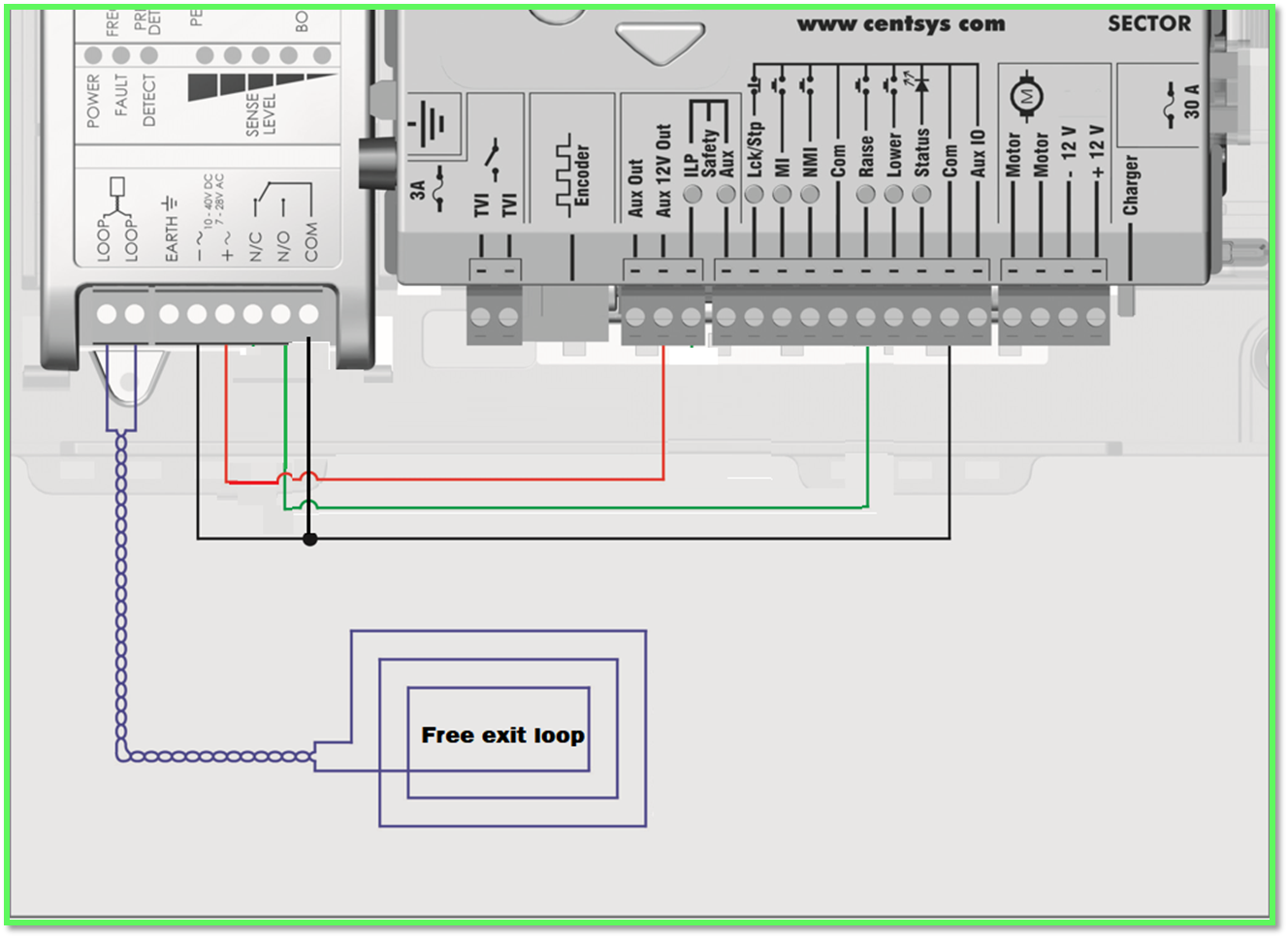
How to wire a Free Exit Loop on Sector - Wiring diagram
Fr
Related Articles
Sector 2 Installation Manual
Please find attached the installation manual for the Sector 2 boom barrier, which includes the following sections: Glossary of terms Product identification Physical installation Onsite electrical wiring Basic controller setup Installation handover ...
How to wire a maglock on to a D5 EVO - Wiring diagram
This wiring diagram illustrates the proper connection of a maglock to the D5 Evo controller, enhancing the security features of your gate motor system. To achieve this, kindly follow the wiring diagram below: Kindy refer to the settings that needs to ...
How to wire a Free Exit Loop on the D10 Sliding Gate Motor.
Below is a diagram showing how a free-exit loop is wired to a Centurion D10 sliding gate operator. This setup will trigger the FRX, allowing the gate to open when a vehicle is standing on the loop for easy exit. Free Exit Loop wired to D5 EVO ...
How to wire a Free Exit Loop on the D5 EVO Sliding Gate Motor.
Below is a diagram showing how a free-exit loop is wired to a Centurion D5 EVO sliding gate operator. This setup will trigger the FRX, allowing the gate to open when a vehicle is standing on the loop for easy exit. Free Exit Loop wired to D5 EVO ...
How to wire a free-exit Loop to an Centurion D5 EVO SMART sliding gate operator
Below is a diagram showing how the free-exit Loop is wired to a Centurion D5 EVO SMART sliding gate operator. This setup will trigger the gate to open when a vehicle is standing on the loop for easy exit.